Electric locomotive EU07
A szócikk a PKP EU07 / EP07 mozdonysorozatáról szól.

A mozdony a valóságban
A PKP EP07 sorozata egy normál nyomtávolságú (1435mm) villanymozdonya, melyet elsősorban személyvonatok továbbításához használnak Lengyelországban. Ezek a mozdonyok az EU07 sorozat felújított mozdonyai, melyek a háború utáni brit mozdonysorozat az EU06 utódai . A mozdonysorozatot a PKP IC illetve a Polregio vasúttársaság működteti.
A sorozat jelenleg a PKP mozdonyflottájának túlnyomó részét adja, melyet könnyű és nehéz személyvonatok továbbítására használnak. [1]
A mozdony a játékban

A mozdony a játék korai hozzáférési szakaszában jelent meg, a sorozattal a játékosok személy- és tehervonatok élén egyaránt játszhatnak.
Az alábbi pályaszámú mozdonyok vezethetőek a játékban:
- EU07-085
- EU07-096
- EP07-135
A mozdony paraméterei:
- Engedélyezett legnagyobb sebesség: 125 Km/h
- Tengelyelrendezés: Bo'Bo' ( A mozdony 2 db forgóvázzal rendelkezik, melyekben mindegyik kerékpár saját vontatómotorral rendelkezik.)
- Nyomtávolság: 1435 mm
- Áramnem: 3kV DC
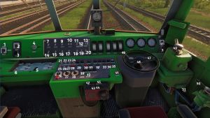
A mozdony vezetőállása

| 1. | Fűtés | 26. | Hátsó áramszedő |
| 2. | Ablaktörlő (a bal és jobb oldali szélvédőrész kön kapcsolóval rendelkezik) | 27. | Vonatfűtés |
| 3. | Ablakmosó | 28. | Tartalék |
| 4. | Vezetőasztal-reteszkulcs | 29. | Légsűrítő túláramvédelem kioldó reléje |
| 5. | Akkumulátor főkapcsoló | 30. | Főmegszakító nyitása |
| 6. | Vezetőállás fűtés | 31. | Főmegszakító zárása |
| 7. | Lábfűtés | 32. | Motor túláramvédelemi relé kioldása |
| 8. | Vezetőállás világítás fénytompítás | 33. | Fűtés és akkumulátor töltőjének túlfeszültségének kioldó reléje |
| 9. | Műszervilágítás fénytompítása | 34. | Kontaktor nyitás |
| 10. | Jelzőfény tompítás | 35. | Fék csúszásgátló |
| 11. | Bal zárfény | 36. | Vonatféknem váltó (G,P,R) |
| 12. | Tartalék | 37. | Teljesítmény kiigazitó (a meghajtott tengelyekhez) |
| 13. | Jobb zárfény | 38. | Áramerősség beállító kapcsolója |
| 14. | Általános világítás | 39. | Fényszóró fénytompítás |
| 15. | Vezetőállás világítás | 40. | Fék kioldás |
| 16. | Műszervilágítás | 41. | Éberségi nyomógomb |
| 17. | Géptér világítás | 42. | Rádió kapcsoló |
| 18. | Fényszóró bal (alsó) | 43. | Rádiócsatorna választókapcsoló |
| 19. | Fényszóró felső (középen) | 44. | Hangerősség (rádió) |
| 20. | Fényszóró jobb (alsó) | 45. | ZEW gombok (rádió) |
| 21. | SHP fénytompítás | 46. | Söntkapcsoló |
| 22. | Első áramszedő | 47. | Irányváltó kapcsoló |
| 23. | Légsűrítő | 48. | Menetszabályzó kontroller |
| 24. | Akkumulátor töltés | 49. | Vonatfék (átmenő fék) |
| 25. | Éberségi fénytompítás | 50. | Mozdonyfék |
| 51. | Kürt |
Cold start procedure
The process of reviving this electric locomotive is identical to EP08
- Make sure you are in cabin A. Open the hatch on the left side of the control panel and switch on the battery.
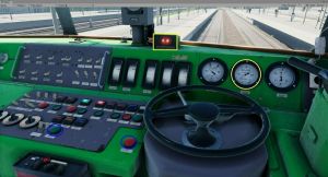
- The battery voltmeter will read approximately 90 volts. The SHP test (automatic safety braking device) will activate. To use it, you must turn the directional lever (blue highlighted) to the forward or reverse position and press the vigilance button.
- Turn the cab activation key - right.
- Turn off the batteries to activate the differential relay. Hold the unlock key until the signal light goes out. If it does not work, check that the power control wheel and shunt control lever are in the zero position.
- Raise the pantographs. Wait for voltage to appear on voltmeter, approximately 3 kV.
- Turn on the main switch. If it does not operate, check that none of the overload relays are active and that the main line pressure is greater than 0.35 MPa.
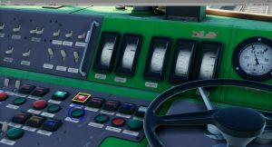
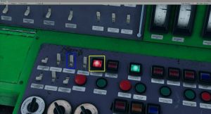
- Turn on the converter (blue highlighted). Wait for the charging current to stabilize (yellow highlighted).
- Turn on the compressor (blue highlighted). Wait for the main tank to fill. Watch the right gauge.
- Turn on the radio and select the desired radio channel.
- Set the train brake lever to the drive or fill position. Hold the release button (blue highlighted left) until the main line pressure reaches 0.5 MPa. Observe the centre pressure gauge.
- Make sure the hand brakes in both cabs have been released. You should see a yellow label in the window that reads "LUZ".
- Release the locomotive brake. Wait for the cylinder pressure to drop to 0 MPa.
- Turn the drive control wheel to position ONE. Wait for the brakes to apply (blue signal light goes out) and the starting circuits to close (orange signal light comes on and current appears on the ammeter).
- Proceed as quickly as possible through the starting resistor positions and try to drive at positions 0, 28 and 43. Then the traction motors will pass all the current. Keep an eye on the ammeters so you don't exceed 600 amps. On the non-resistance positions you can increase the speed by starting the shunt with the shift handle. Beyond position 28 you can go up to 1200A
- To brake, turn both the control wheel and the shunting handle to zero and pull the train brake handle towards you. Depending on the desired braking force, relieve 0.05-0.2 MPa of pressure from the main line. Observe the middle pressure gauge. The left one shows only the pressure in the locomotive brake cylinders [2].
Locomotive malfunctions
- Alarm/SHP on. Press the vigilance button. If both systems are activated simultaneously, it must be pressed twice. If there is an insufficient response to the visual and audible warning, emergency braking is activated. If the main line pressure has been successfully reduced below 0.35 MPa, you must set the service brake handle to the drive or fill position and hold the release button until the pressure rises to 0.5 MPa.

EP07 - ignoring SHP
- Rare overload of traction motors switched on. If the current exceeds 600 A, the overload relay will trip. Set the control wheel and maneuvering handle to zero. Press the traction motor overload relay unlock button. The red signal light goes out.

- Rare compressor overload switched on. This relay will trip if you turn on the compressor before the converter power supply stabilizes. Turn off the compressor and converter. Disable the compressor overload relay. Turn on the converter. Wait for the voltage to stabilize. Switch on the compressor.

Gallery
- Screenshots from the game (without zoom)
-
EU07, Image creator: Tonda
-
EU07 together with Elf, Image by: Hawis
-
Image creator Roman

