Lokomotywa elektryczna EP08
Ten artykuł dotyczy lokomotywy elektrycznej EP08.

Lokomotywa w prawdziwym życiu
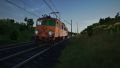
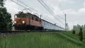
EP08 (typ 4Ea oraz 102E) - elektryczna lokomotywa o normalnym rozstawie kół używana do transportu pasażerskiego. Produkowana w 1972-1976 w fabryce Pafawag we Wrocławiu. Była nazywana "świnką" ze względu na jej kolor...
Lokomotywy EP08 były wzorowane na EU06 oraz EU07. Zmiany w wyglądzie miały na celu zwiększenie prędkości maksymalnej. Zostało to osiągnięte przez zmianę stosunku zębatek z 79:18 na 77:24. Na początku prędkość maksymalna wynosiła 160km/h, ale ze względu na szybsze niszczenie elementów, została zmniejszona do 140. Poza zmianą zębatek, została wymieniona też electrified locomotives of this series were based on the design of the EU06 and EU07 series. The design changes were intended to allow for higher speeds - this was achieved by changing the gear ratio from 79:18 to 77:24. The assumed theoretical top speed of 160 km/h was not introduced because the vehicle then acquires poor handling characteristics and wears out the material more quickly. In addition to the gearbox change, new engines, a different hollow shaft bearing and other upgrades were also used. Type 4Ea locomotives (Nos. 002 - 005) used standard EU07 plain bearings, while the newer Type 102E (Nos. 001 and 006 - 015) were fitted with roller bearings. The original EP08 construction programme envisaged the building of 100 of these cars, but this was not completed. Between 1972 and 1976 Pafawag produced only 15 units (Roman Staszałek lists 14). The end of production was due to the lack of foreign currency to buy bearings abroad [1].
In-game locomotive

This in-game electric locomotive was added in the 19.02.2023 update and players can run this locomotive on EC trains, and the locomotive offers an alternative to the EU07 electric locomotive.
Serial numbers of locomotives that can be driven:
- EP08-001
Parameters of this locomotive
- Maximum speed 140 Km/h
EP08 serving the relevant connections
| Train number | Train display
on the map |
Departure
station |
Destination
station |
|---|---|---|---|
| 41102 | 02:41 | Katowice | Warsaw |
| 41106 | 04:41 | Katowice | Warsaw |
| 41110 | 06:41 | Katowice | Warsaw |
| 41114 | 08:41 | Katowice | Warsaw |
| 41128 | 15:41 | Katowice | Warsaw |
| 41122 | 12:41 | Katowice | Warsaw |
| 41126 | 14:41 | Katowice | Warsaw |
| 41130 | 16:41 | Katowice | Warsaw |
| 41134 | 18:41 | Katowice | Warsaw |
| 41138 | 20:41 | Katowice | Warsaw |
| 41142 | 22:41 | Katowice | Warsaw |
| 41146 | 00:41 | Katowice | Warsaw |
| 14101 | 00:28 | Warsaw | Katowice |
| 14105 | 02:28 | Warsaw | Katowice |
| 14109 | 04:28 | Warsaw | Katowice |
| 14113 | 06:28 | Warsaw | Katowice |
| 14117 | 08:28 | Warsaw | Katowice |
| 14121 | 10:28 | Warsaw | Katowice |
| 14125 | 12:28 | Warsaw | Katowice |
| 14129 | 14:28 | Warsaw | Katowice |
| 14133 | 16:28 | Warsaw | Katowice |
| 14137 | 18:28 | Warsaw | Katowice |
| 14141 | 20:28 | Warsaw | Katowice |
| 14145 | 22:28 | Warsaw | Katowice |
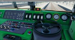
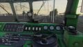
Interior of the locomotive

| 1. | Stove | 26. | Pantograph back |
| 2. | Wiper | 27. | Train heating |
| 3. | Washer | 28. | Reserve |
| 4. | Cabin activation | 29. | Unlock compressors overload realy |
| 5. | Battery | 30. | Open main switch |
| 6. | Cabin heating | 31. | Close main switch |
| 7. | Legs heating | 32. | Unlock traction motors overload relay |
| 8. | Cab lighting dimming | 33. | Unlock overload relay of converters and heating |
| 9. | Instrument lighting dimming | 34. | Open line contactors |
| 10. | Signal lights dimming | 35. | Antislipping brake |
| 11. | Endsignal left | 36. | Brake delay setting |
| 12. | Reserve | 37. | Adjust forces to wheels pressure |
| 13. | Endsignal right | 38. | Current setting |
| 14. | Overall lighting | 39. | Light dimming |
| 15. | Cab lighting | 40. | Brake releaser |
| 16. | Instrument lighting | 41. | Vigilance button |
| 17. | High voltage compartment light | 42. | Radio power switch |
| 18. | Headlamp left | 43. | Radio channel select |
| 19. | Headlamp top | 44. | Volume |
| 20. | Headlamp right | 45. | ZEW buttons |
| 21. | SHP dimming | 46. | Shunt regulator |
| 22. | Pantograph front | 47. | Direction control |
| 23. | Compressor | 48. | Drive handle |
| 24. | Converter | 49. | Service brake |
| 25. | Alerter dimming | 50. | Local brake |
| 51. | Horn |
Cold start procedure
The process of reviving this electric locomotive is identical to that of the EU07 / EP07 locomotive.
- Make sure you are in cab A. Open the hatch on the left side of the control panel and switch on the battery.
- The battery voltmeter will read approximately 90 volts. The SHP test (automatic safety braking device) will activate. To use it, you must turn the directional lever (blue highlighted) to the forward or reverse position and press the vigilance button.
- Turn the cab activation key - right.
- Turning off the batteries will activate the differential relay. Hold the unlock key until the signal light goes out. If it does not work, check that the power control wheel and shunt control lever are in the zero position.
- Raise the pantographs. Wait for voltage to appear on voltmeter, approximately 3 kV.
- Turn on the main switch. If it does not operate, check that none of the overload relays are active and that the main line pressure is greater than 0.35 MPa.
- Turn on the converter (blue highlighted). Wait for the charging current to stabilize (yellow highlighted).
- Switch on the compressor (blue highlighted). Wait for the main tank to fill. Watch the right gauge.
- Turn on the radio and select the desired radio channel.
- Set the train brake lever to the drive or fill position. Hold the release button (blue highlighted left) until the main line pressure reaches 0.5 MPa. Observe the centre pressure gauge.
- Make sure the hand brakes in both cabs have been released. You should see a yellow label in the window that reads "LUZ".
- Release the locomotive brake. Wait for the cylinder pressure to drop to 0 MPa.
- Turn the drive control wheel to position ONE. Wait for the brakes to apply (blue signal light goes out) and the starting circuits to close (orange signal light comes on and current appears on the ammeter).
- Proceed as quickly as possible through the starting resistor positions and try to drive at positions 0, 28 and 43. Then the traction motors will pass all the current. Keep an eye on the ammeters so you don't exceed 600 amps. On the non-resistance positions you can increase the speed by starting the shunt with the shift handle. Beyond position 28 you can go up to 1200A
- To brake, turn both the control wheel and the shunting handle to zero and pull the train brake handle towards you. Depending on the desired braking force, relieve 0.05-0.2 MPa of pressure from the main line. Observe the middle pressure gauge. The left one shows only the pressure in the locomotive brake cylinders [2].
Locomotive malfunctions
- Alarm/SHP on. Press the vigilance button. If both systems are activated simultaneously, it must be pressed twice. If there is insufficient response to visual and audible warning, emergency braking is activated. If the main line pressure has been successfully reduced below 0.35 MPa, you must set the service brake handle to the drive or fill position and hold the release button until the pressure rises to 0.5 MPa.
EP07 - ignoring SHP

- Rare overload of traction motors switched on. If the current exceeds 600 A, the overload relay will trip. Set the control wheel and maneuvering handle to zero. Press the traction motor overload relay unlock button. The red signal light goes out.

- Rare compressor overload switched on. This relay will trip if you turn on the compressor before the converter power supply stabilizes. Turn off the compressor and converter. Disable the compressor overload relay. Turn on the converter. Wait for the voltage to stabilize. Switch on the compressor.

Gallery
- Screenshots from the game (without zoom)
-
-
-
-
 Author MilanSVK
 -