ETCS: Difference between revisions
No edit summary |
No edit summary |
||
| Line 371: | Line 371: | ||
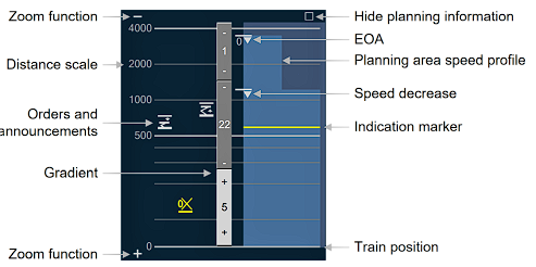
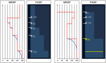
====DMI - Planning area==== | ====DMI - Planning area==== | ||
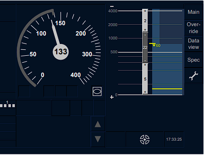
[[File:dmi planarea1.png|link=https://simrail.cz/wiki/File:dmi%20planarea1.png]][[File:dmi planarea2.png|link=https://simrail.cz/wiki/File:dmi%20planarea2.png]][[File:MRSP-PASP.png|left| | [[File:dmi planarea1.png|link=https://simrail.cz/wiki/File:dmi%20planarea1.png]][[File:dmi planarea2.png|link=https://simrail.cz/wiki/File:dmi%20planarea2.png]][[File:MRSP-PASP.png|left|436x436px]] | ||
[[File:ETCSSnímek obrazovky 2023-08-01 215439.png|link=https://simrail.cz/wiki/File:ETCSSn%C3%ADmek%20obrazovky%202023-08-01%20215439.png|center]] | [[File:ETCSSnímek obrazovky 2023-08-01 215439.png|link=https://simrail.cz/wiki/File:ETCSSn%C3%ADmek%20obrazovky%202023-08-01%20215439.png|center]] | ||
=ETCS in SimRail= | =ETCS in SimRail= | ||
Revision as of 20:58, 1 August 2023
ETCS
ERTMS ("European Rail Traffic Management System") is a major industrial project being implemented by the European Union, a project which will make rail transport safer and more competitive.
Over the last years, ERTMS has become a trending topic when talking about European railways. But what is it exactly and what are its goals?
ERTMS, which stands for ‘European Railway Traffic Management System’, is the European standard for the Automatic Train Protection (ATP) and command and control systems. It creates an interoperable railway system in Europe that is more efficient and safer. It contributes to making rail operation between the Member States much easier and is an essential element of the Single European Railway Area.
ETCS functionality
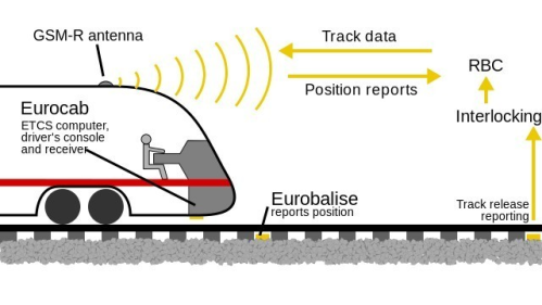
The Radio Block Centre (RBC) and the Eurobalises in the second application level form the trackside part of ETCS. The RBC monitors and communicates with individual trains. It knows the position, direction of travel and speed of the trains and reserves a clear, safe space for their onward movement. It monitors whether the driver of the train maintains the speed and reacts correctly to the situation on the track. Knows how to stop a train before a stop signal or when the driver is indisposed. For the system to work well, the infrastructure and vehicles of all carriers wishing to run on such a line must be equipped over time.
There is also a simpler version of the track-side part of ETCS (first application level) which does not require GSM-R radio system to communicate with trains and is particularly suitable for less congested routes.
ETCS levels
Level 0
Level 0 applies when an ETCS-fitted vehicle is used on a non-ETCS route. The trainborne equipment monitors the maximum speed of that type of train. The train driver observes the trackside signals. Since signals can have different meanings on different railways, this level places additional requirements on drivers' training. If the train has left a higher-level ETCS, it might be limited in speed globally by the last balises encountered.
Level 1
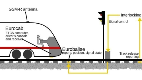
involves continuous supervision of train movement (i.e. the onboard computer is continuously supervising the maximum permitted speed and calculating the braking curve to the end of movement authority) while non-continuous communication occurs between train and trackside, generally through Eurobalises.
Lineside signals are necessary. Train detection and train integrity checks (i.e. the train is complete and has not been accidentally split) are performed by the trackside equipment beyond the scope of ERTMS.
Level 2
Involves continuous supervision of train movement with constant communication via GSM-R between the train and trackside.
Lineside signals are optional in this case, and train detection and train integrity checks are performed by the trackside equipment beyond the scope of ERTMS.
Level 3
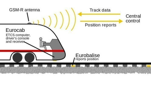
Involves continuous train supervision with continuous communication between the train and trackside. The main difference with Level 2 is that train location and integrity are managed within the scope of the ERTMS system, i.e. there is no need for lineside signals or train detection systems on the trackside other than Eurobalises. Train integrity is supervised by the train.
In addition, there are two more levels: Level 0, which applies to trains equipped with ETCS running on non-equipped lines; and Level STM, which is meant for trains equipped with ETCS running on tracks where the Class B system needs to be operated. With regard to the STM level, ETCS acts as an interface between the driver and the national ATP.
ETCS LC
Low cost option for local routes. The system should work the same as L3, only the number of balises would be minimized. The balises would be used only in circuits with track branching, satellite navigation for locating the position of the train on the line is also considered.
What does ETCS consist of?
The ETCS equipment consists of a track-side and an on-board part. The information between them is in the form of data transmissions.
- Mobile or on-board part is mounted on vehicles
- Trackside or infrastructure part is installed along the tracks
Some variants of ETCS also use the GSM-R wireless network for communication between the track-side and mobile parts.
Operation modes in ETCS
DMI symbols
Other symbols
| Limited Supervision frame | Geographical Position | ||
| LX not protected | Acknowledgement | ||
| Toggling function for speed/distance information | Toggling function for tunnel stopping area | ||
| Track Ahead Free |
Level symbols
Status symbols
Planing area / Track Condition symbols
DMI - Planning area
ETCS in SimRail
In Poland, only part of the CMK section (Grodzisk Mazowiecki - Idzikowice) and the section Włoszczowa Północ - Zawiercie are operated in Full Control - L2 mode.
ETCS-equipped locomotives and units
- ED250
- Dragon
Some Text....
text
Used materials:
Wikipedia, SZDC (CZ), ec.europa.eu, ERA_ERTMS_015560
